Fingertip Sensor for Haptic Manipulation
Alongside my main research project (the Robotic Hand), I continued the current project on a fingertip sensor. The motivation of the project was to develop a sensor to be mounted at the end of a robotic hand/end-effector that can sense the direction of external forces and the location of the contact. This work was a continuation of Michael Chuah’s PhD research and Lindsey Epstein’s Master’s thesis. While I worked mostly on the manufacturing, training software, and integration, Andrew Salatous and Adi Mehrota worked on building the testing platform and the sensor electronics.
As this project required reverse engineering and improving an existing system, it focused more on data analysis, documentation, system-design, manufacturing, and troubleshooting.
Problem Statement
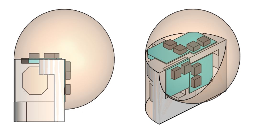
The goal is to create a sensor with many design requirements, eventually, the paradigm of pressure sensor embedded in an elastomer was settled on:
-
Normal and Shear sensing:
In addition to the sensing location, the magnitude of forces are vital to determine the nature of contact with the environment. Force Sensitive Resistors (FSR) sense forces as it changes the resistivity of the conductive polymer, but due to delamination from shear forces it was ruled out. Tactile sensing arrays are usually in a flat form does well in location sensing but not as well for multi-axis force measuring. -
Robust to high impacts:
Since the focus of our lab is high force impacts especially as a hand explores the environment, robustness is quite important. Although force-torque sensors are very accurate, don’t survive impacts well due to their high stiffness. -
Lightweight and insensitive to noise:
As the application is at the end of the fingers, the lightweight and compact nature are crucial. Being insensitive to noise is important as the sensor will be moving around quickly. This is another reason why force-torque sensor, which are generally heavier, would introduce a large amount of inertial noise at high accelerations. -
High-frequency Response:
High-frequency response is needed as contact and collisions happen at very short time scales. The sensors in the end were able to operate at 200hz with possibility of going to 500hz. This was also the reason to rule out optic-based sensing that relies on a camera to map deformations, which would be too slow for our application.
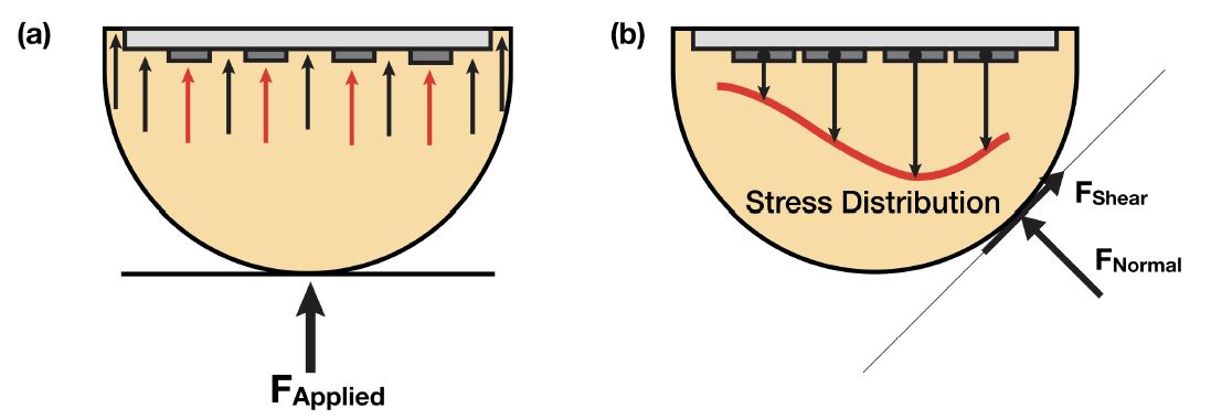
How this technology works is shown below, where the stress distribution of the embedded sensors can be mapped to the forces and location of contact.
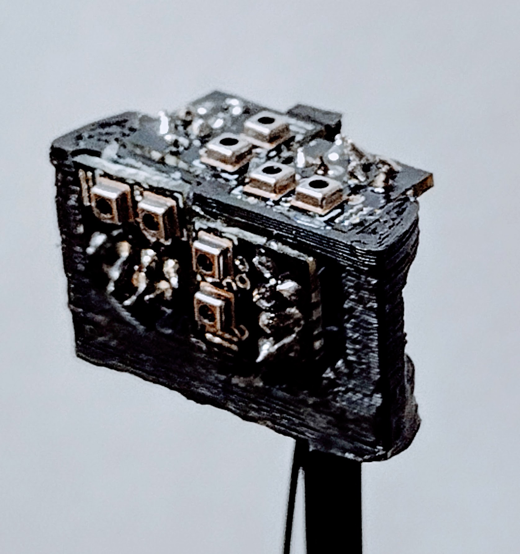
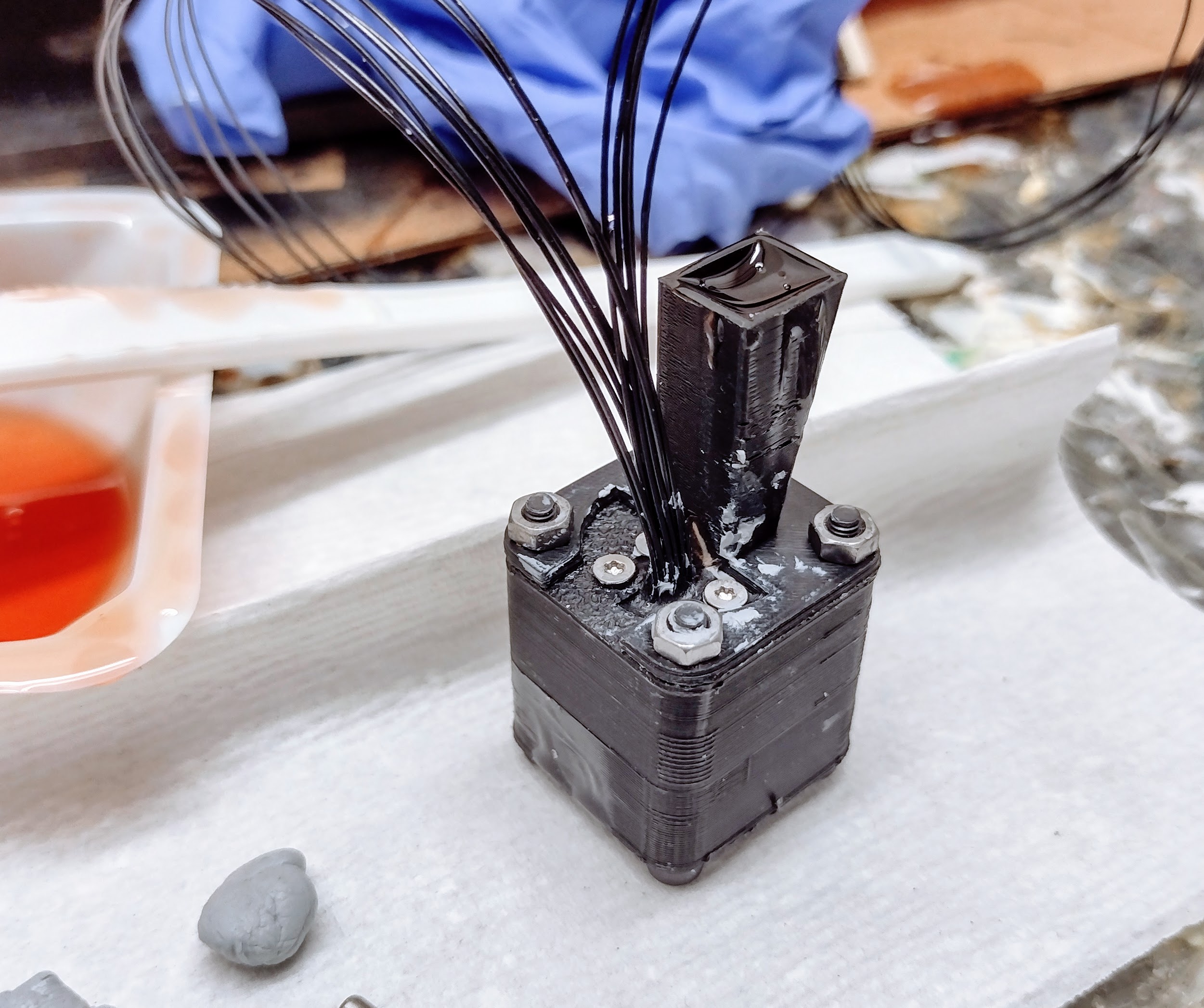
Upgrade to the Manufacturing Process
After reverse-engineering how the system worked, I decided to rebuild the system from the ground up as the codebase was too messy and the testing platform was too complex to operate. Almost the whole process was changed: the delta arm replacing the CNC mill testing platform, Matlab and python replacing LabView and C++. As a result, it gave a lot of opportunities to improve the process along with a lot of new issues to troubleshoot if the methodology deviated too much. (Many images in the old sensor process were taken from Lindsey’s thesis).
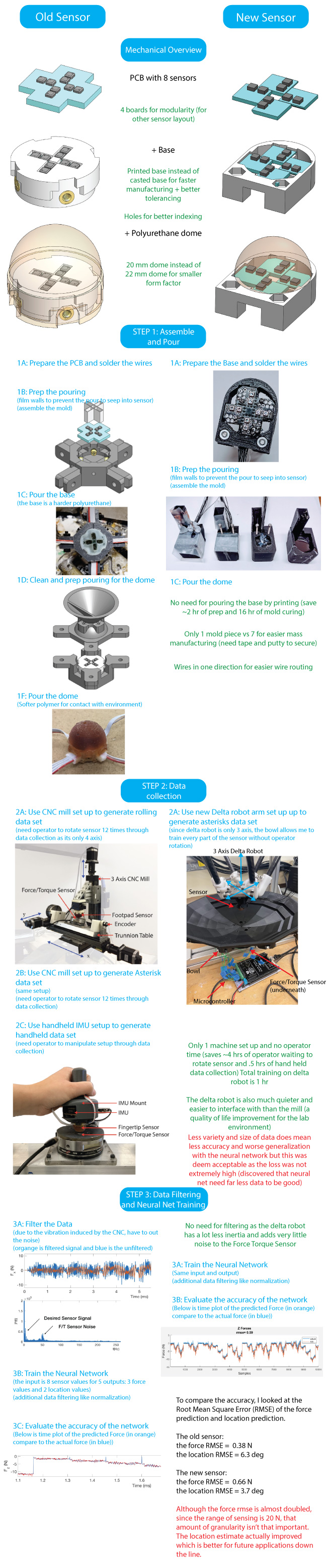
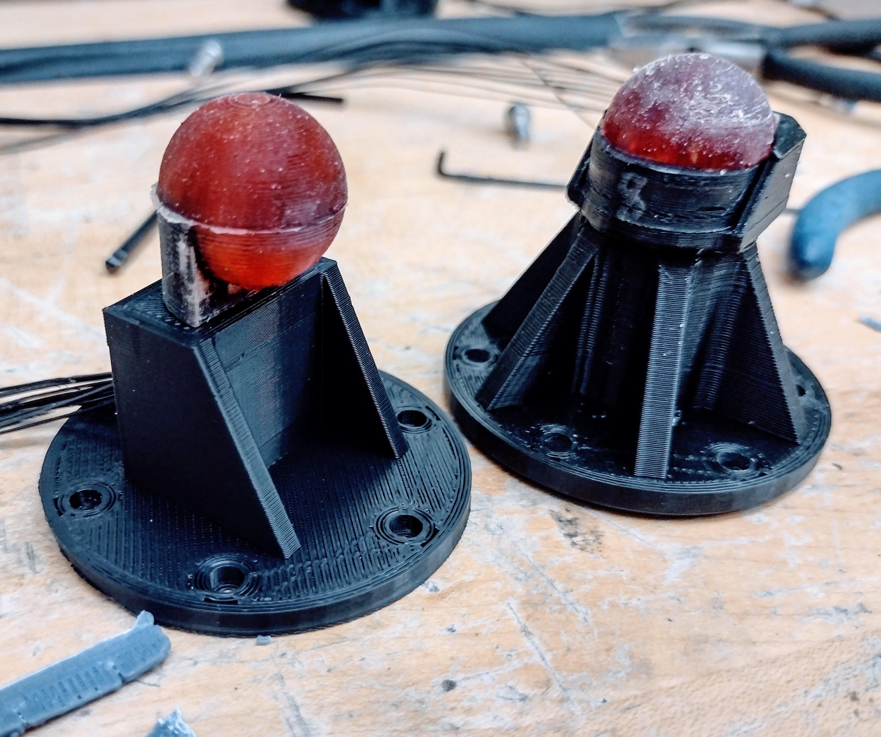
Plans for future sensor
The half-sphere design is quite useful in many applications (see below) but it can be augmented for more sensing area. This new design has around 2.5 times more sensing area than the current design. This allows for more surface area to sense contact and manipulate objects. An initial prototype was made from plastic for the test, the future ones will be made with an aluminum base for better tolerancing and mass-manufacturability.
Applications
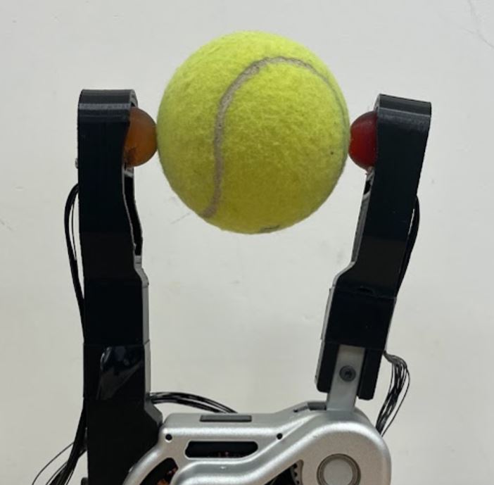
This sensor’s high-frequency bandwidth and sensing capabilities allow it for many possible applications in manipulation. In the first video, the finger is acting as a virtual magnet as it attempts to maintain a force of 3 newtons in the direction of contact. The effect is a very fast contact following demo that can lead to fast in-hand object manipulation with coordination with another finger and sensor.
This demo is work done by Elijah Stanger-Jones and Andrew SaLatous, which uses the sensor to do rapid re-grasping. The experiment is set up so the robot reaches forward to grasp without seeing the object using vision. When it contacts the cylindrical shape, the program calculates the direction of the contact and automatically positions the hand to antipodal points. The demo requires high-frequency sensing to avoid collisions that would perturb or damage the environment, the video below is slowed down to 1/8 the actual speed.
Troubleshooting
A big portion of the process was the troubleshooting aspect as most of the existing system hasn’t been continued since the last student had graduated. To manage the new and old bugs that appeared was good documentation and data analysis. Below are some of the more challenging problems to troubleshoot.
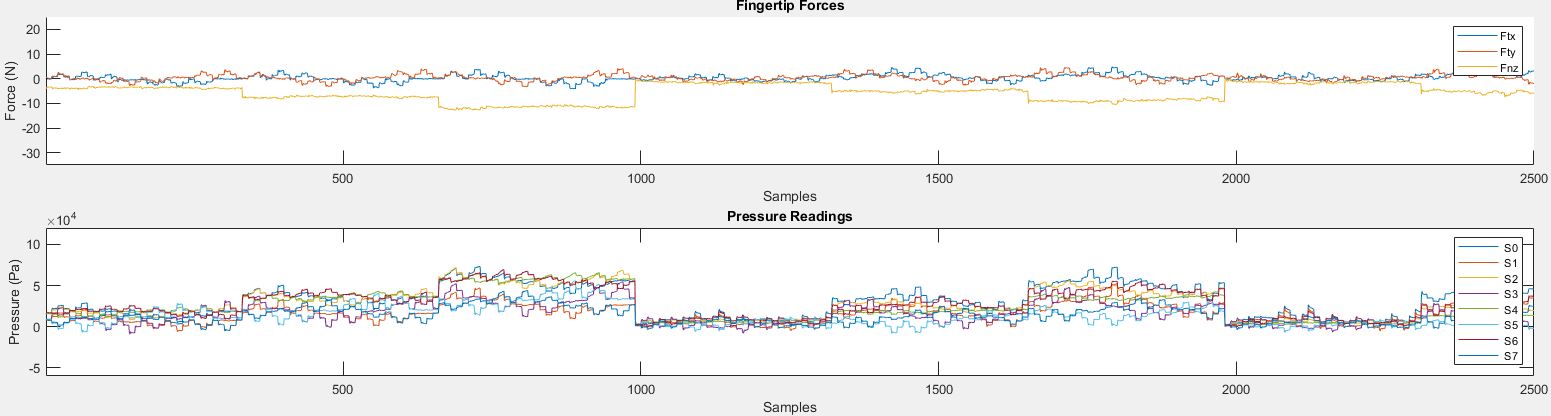
During the beginning of the testing, I discovered that the sensor values are depreciating over time and usage.
In this picture below, the top shows the graph of fingertip forces, and the bottom is a graph of pressure from the 8 sensors on 1 fingertip sensor.
You can see the clear correlation of forces to pressure values.
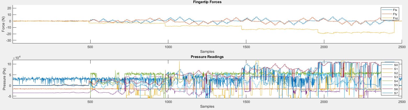
A month later, after running the trial, the pressure sensor no longer correlate well to the pressure values.
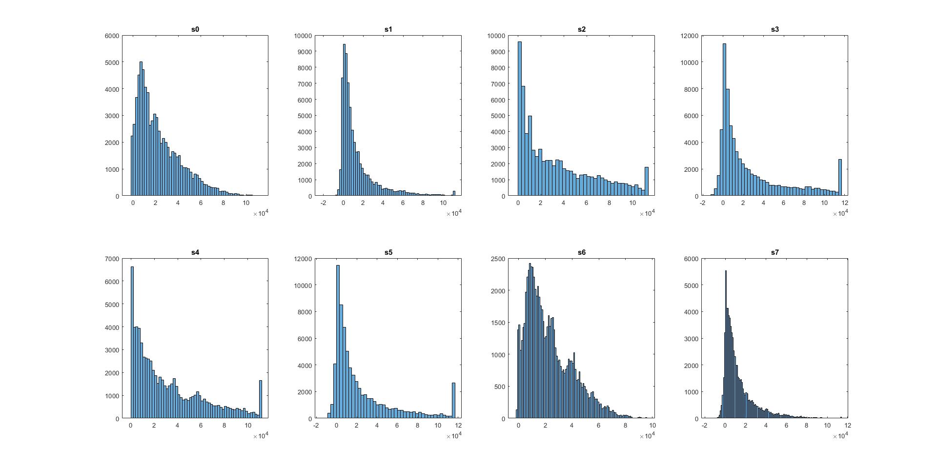
Since this is just a small snapshot of the whole training process, I graph the distribution of values in each of the 8 pressure sensors on 1 fingertip sensor.
This was the one from a month earlier:
Compare that to the one a month later:
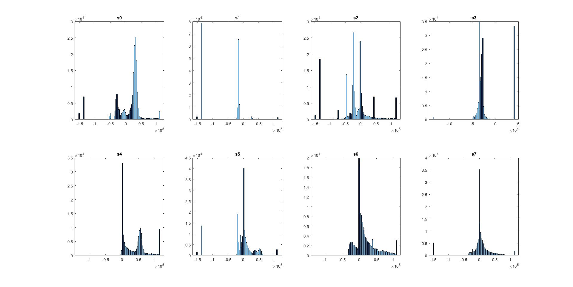
From the distribution, we can see the one from a month earlier was much smoother, giving great resolution in the data, compared to the one from a month later.
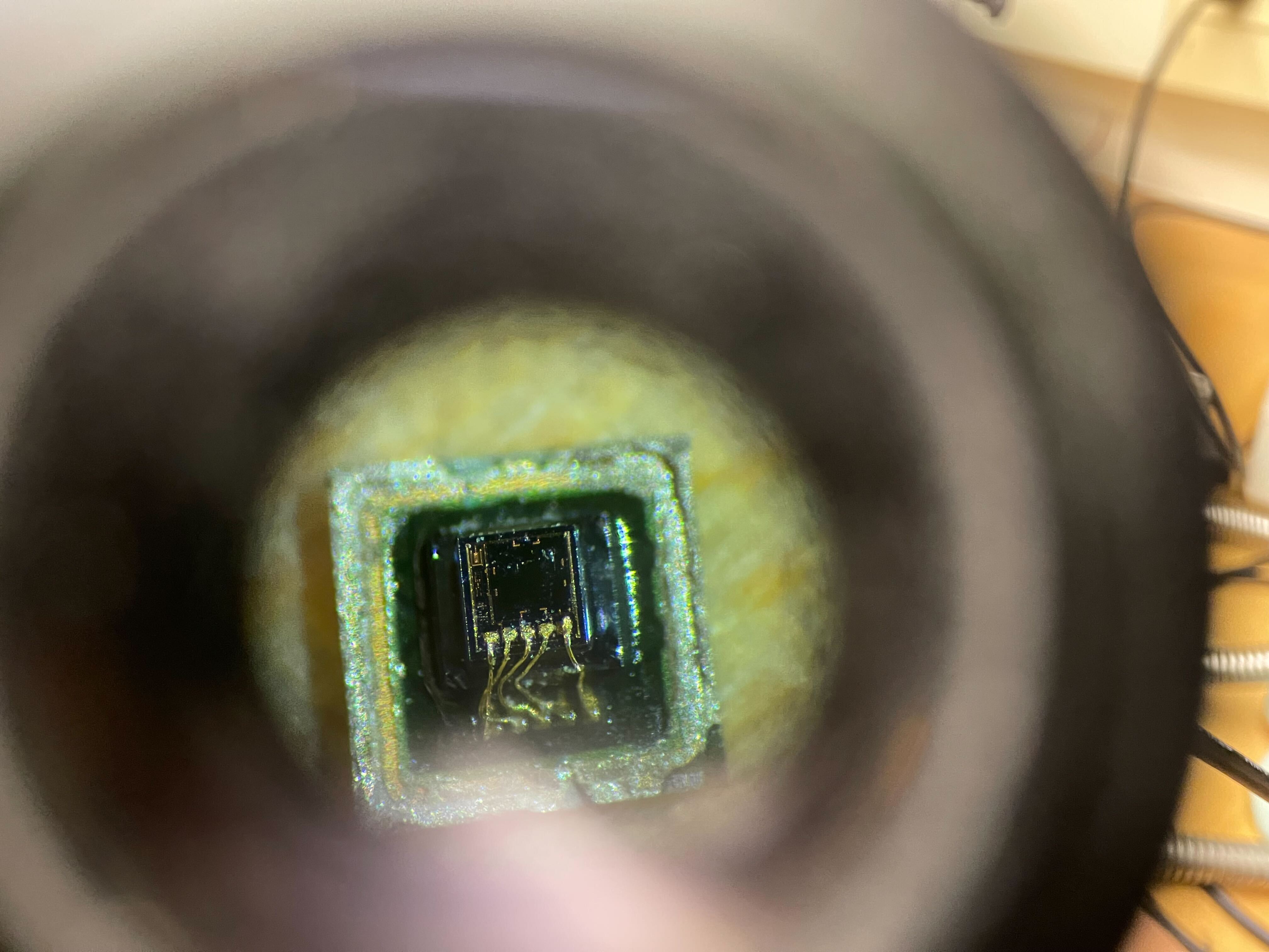
After investigation, the issue was that this resulted from us removing a protective covering (shown below) from the sensor in order for the elastomer to make better contact with the sensing element.
After inspection through a microscope of a dissected sensor, you can see that the wires to the piezo-electric element were damaged over repeated usage.
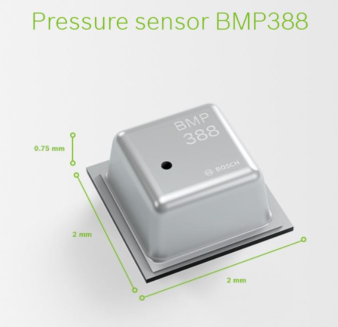
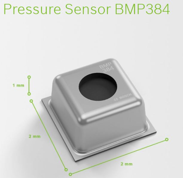
 This was fixed by replacing the pressure sensor with a model that has a bigger hole so that the elastomer could achieve good contact without taking the protective covering off.
Another issue I found was that the material of the gripper slowly changes over time. Realizing that this was most likely the degradation of the polyurethane material, I purchased a new batch and did some testing. Although you can feel that the older material was more compliant and took longer to bounce back (more hysteresis), it’s best to quantify this.
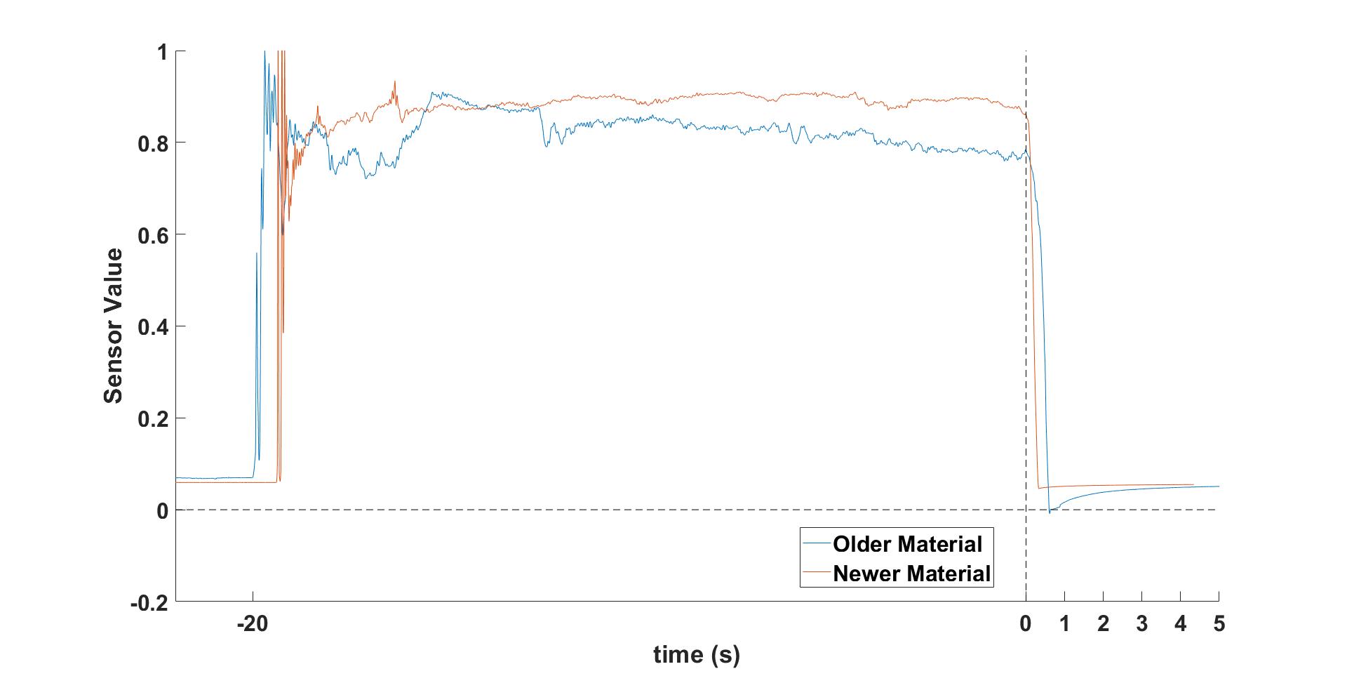
I left a weight on the gripper for ~20 seconds and then took it off to plot the change in the sensor value.
In the graph, we can see that the newer material took .4 seconds for the values to drop back compared to the .85 seconds for the older material.
The older material took even longer to fully restore to the non-load value (3.5 seconds vs 0.8 seconds).
As the gripper will be used to exert sustained forces and make rapid contacts, this hysteresis was a huge problem.
Luckily, the fix is simply to watch the shelf-life of the material and benchmark the hysteresis.
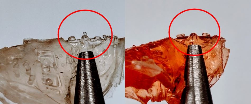
Although the new material fixed the hysteresis problem, I have found that the newer fingertip sensor had many dead values. Of the 8 pressure sensors on each fingertip, some would not respond to pressures even though they are fully functioning. After thorough testing and a dissection of the new sensors, I found that the new material was not seeping into the pressure sensor and making contact. Funnily enough, the old material was much less hydrophobic and was able to squeeze into the hole in the pressure sensor, avoiding this problem.
I peeled off the polyurethane to examine the contact between the pressure sensor and the rubber. In the image below, you can see that the newer material (on left) does not form a mushroom cap like the older material, meaning it does not fully seep into the pressure sensor. The way that this was fixed was to de-gas (the process of vacuuming out the air that helps draw the material into cavities) for much longer (20 min vs 5 min) to ensure the new material flows better.