Co-Robotic Precision Irrigation Device
This research was on a novel co-robotic device that adjusts flow emitter valves for precision irrigation. The work was done under Professor Ken Goldberg’s Automation Lab (Autolab) in my 1st year at Berkeley.
I worked on designing a vision tracking system to quantify grasping uncertainty and rapid-protopying to develop the device. This work was published in IEEE’s International Conference on Automation Science and Engineering (Case 2016).
Motivation and Concept
Agricultural irrigation uses 85% of the world’s freshwater. Drip irrigation is commonly used to service a wide area of plants, however, the method is prone to inefficiencies and overwatering. The goal of the research is to propose a novel hand held device that will adjust drip emitter valves.
Using overhead UAV or satellite imaging to determine which areas of plant need more or less water, this device will then be deployed to adjust valves for certain areas to prevent over and underwatering. Although the design is of a hand held device, the hope is to attach it onto a robotic vehicle that can meticulously service wide areas instead of a human.
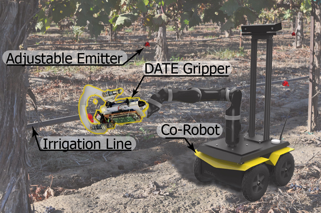
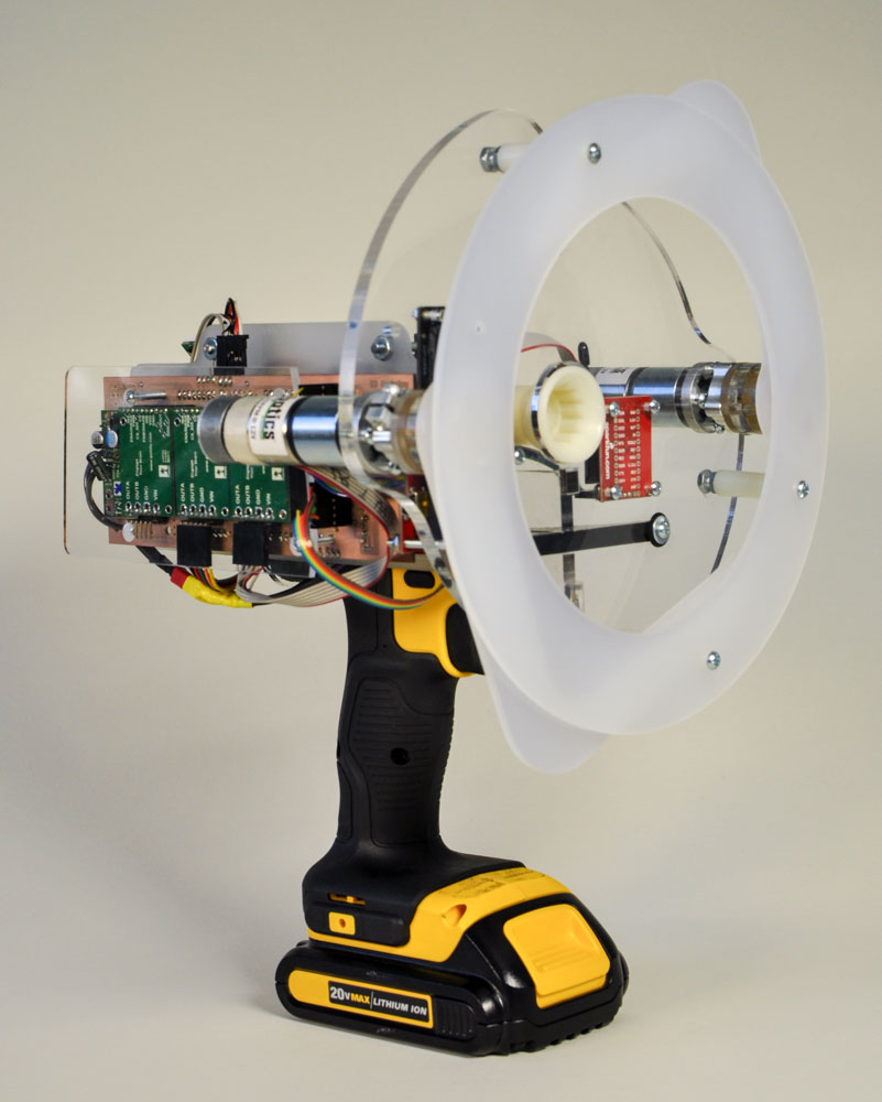
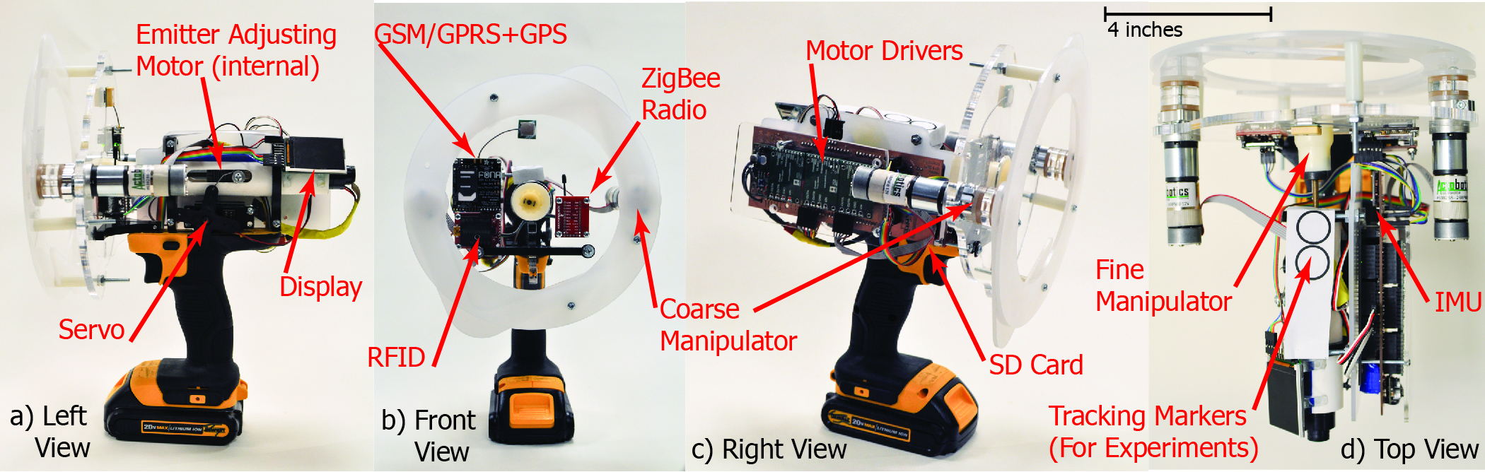
Due to the small size of these end effector, the device presented has two mechanisms to align and adjust individual emitter valves. The course adjustment utilize plastic arms that will center the device to the valve while the fine adjustment uses a flexible coupling for any angular deviations.
Vision Tracking System and Testing
It was vital to experimentally evaluate the effectiveness of the adjustment mechanism to quantify what range of linear and angular deviation will the device correct for and still be able to perform properly. I designed the vision tracking system that will analyze the overhead image to locate the device and calculate its angular and linear misalignments through multiple grasping trials.
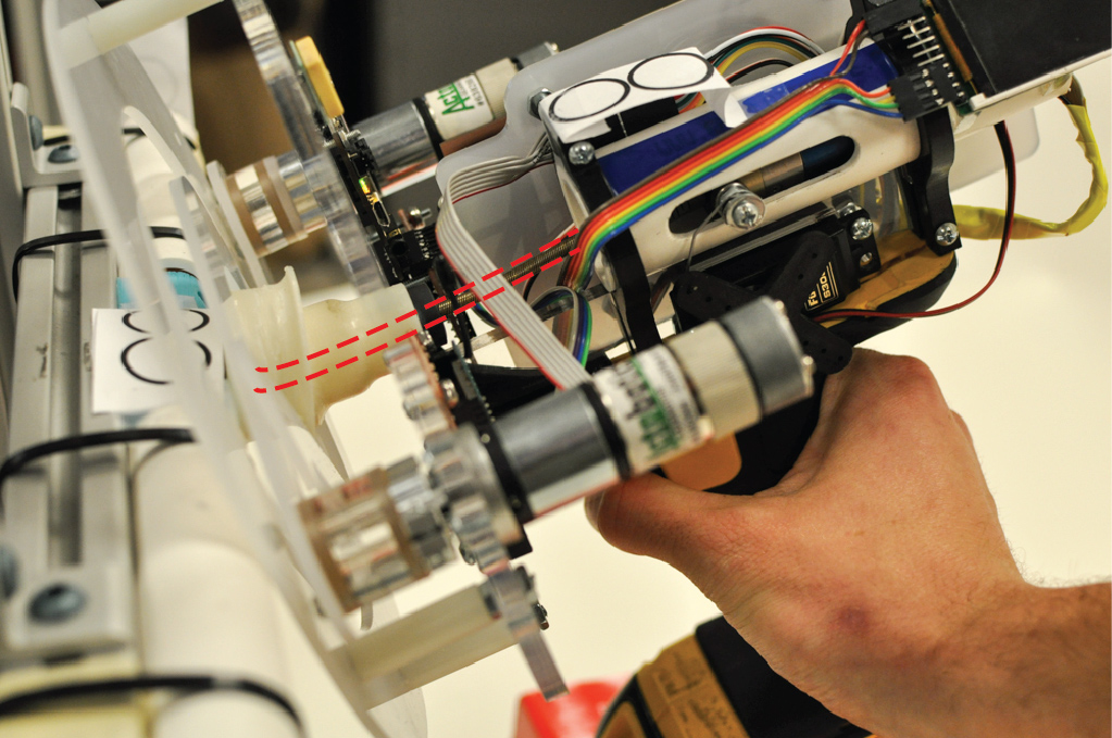
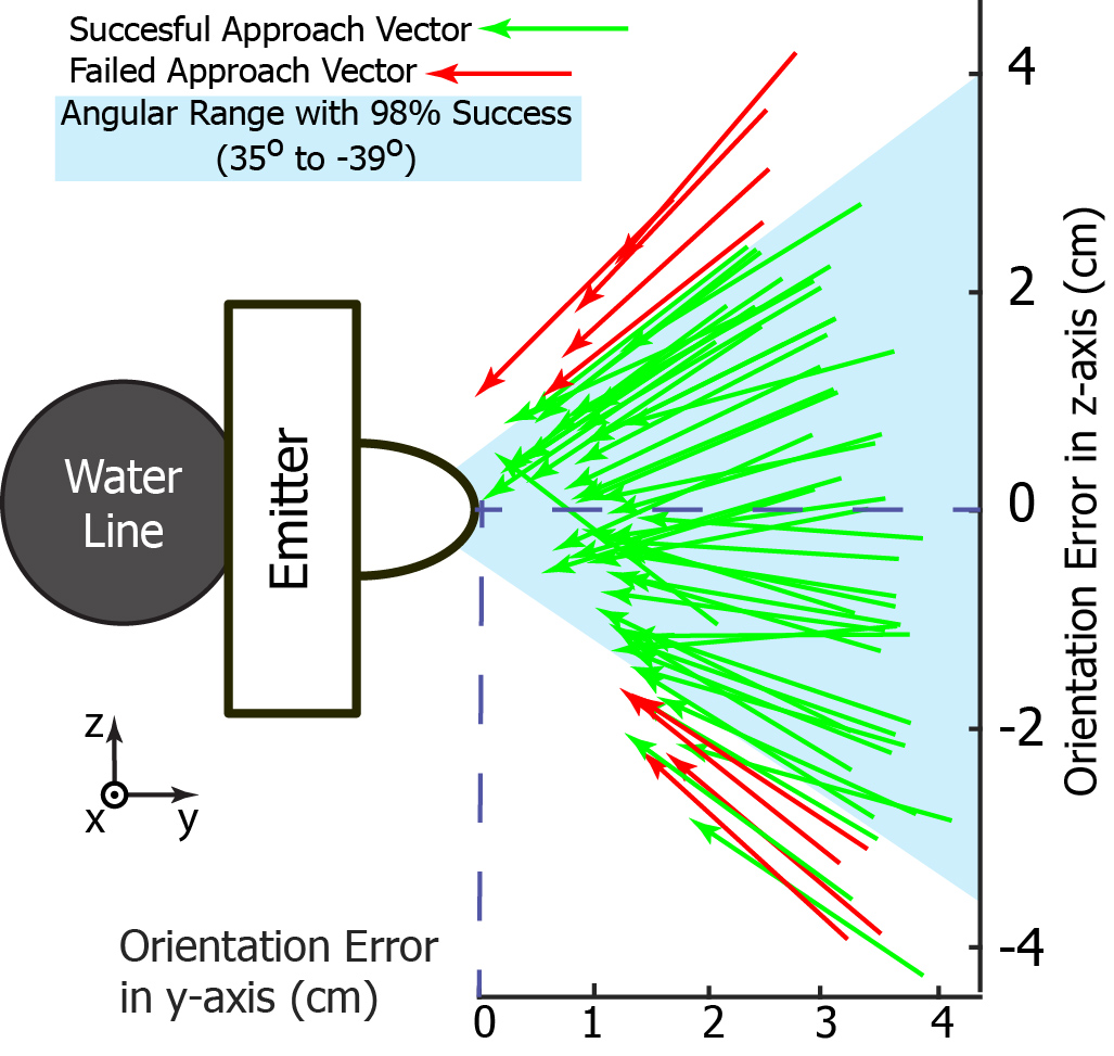
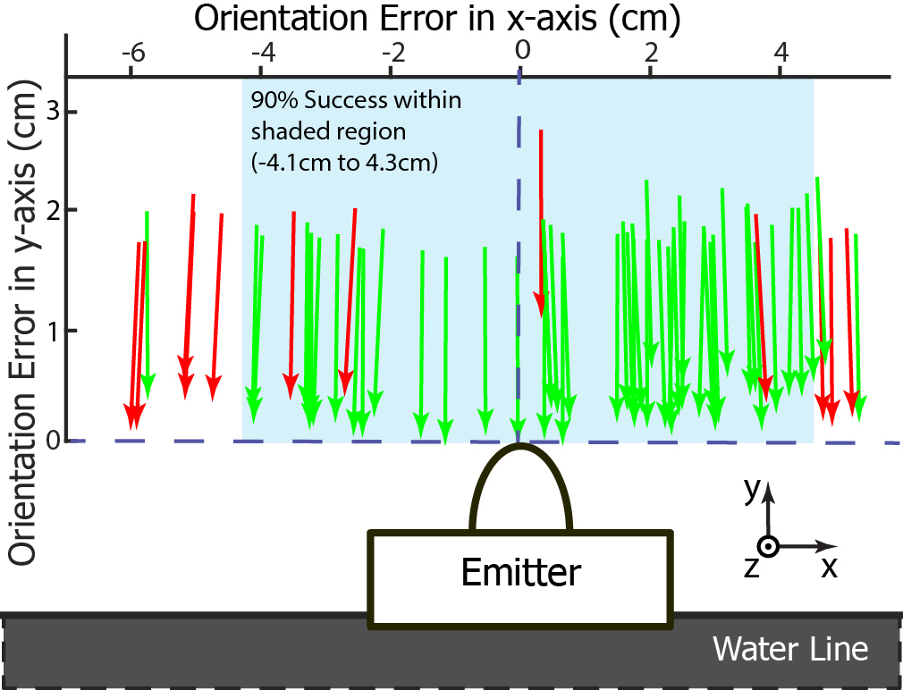
Above shows the experiments where the fine adjustment compensated for the angular deviation and resulted in a successful grasp. Below shows the image analysis (using Matlab) that calculated the magnitude of the approach vector’s angular and linear deviations.
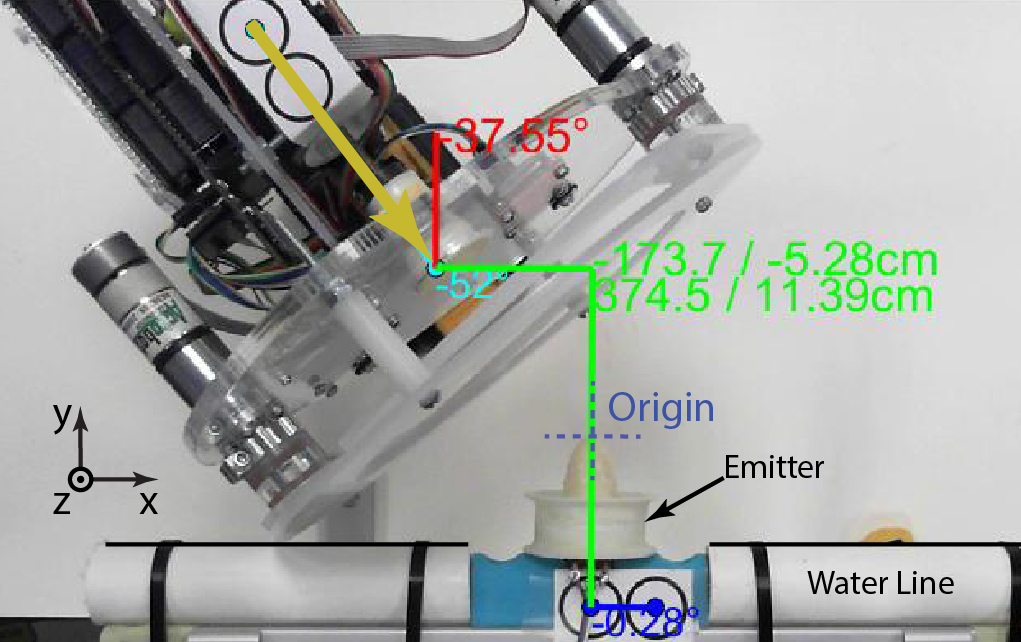
After 60 grasping trials, the program aggregates the linear and angular orientation errors to compute a 90% success region where the adjustment can compensate for.